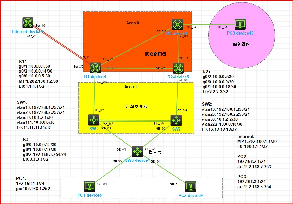
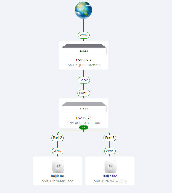
实验拓扑
实验需求 i .按照图示配置 IP 地址
1
2
3
4
5
6
7
8
9
10
11
12
13
14
15
16
17
18
19
20
21
22
23
24
25
26
27
28
29
30
31
32
33
34
35
36
37
38
39
40
41
42
43
44
45
46
47
48
49
50
51
52
53
54
55
56
57
58
59
60
61
62
63
64
65
66
67
68
69
70
71
72
73
74
75
SW1: interface LoopBack0 ip address 11.11.11.11 255.255.255.255 interface Vlan-interface10 ip address 192.168.1.252 255.255.255.0 interface Vlan-interface20 ip address 192.168.2.252 255.255.255.0 interface Vlan-interface30 ip address 10.1.2.1 255.255.255.252 interface Vlan-interface111 ip address 10.0.0.6 255.255.255.252 SW2: interface LoopBack0 ip address 12.12.12.12 255.255.255.255 interface Vlan-interface10 ip address 192.168.1.253 255.255.255.0 interface Vlan-interface20 ip address 192.168.2.253 255.255.255.0 interface Vlan-interface30 ip address 10.1.2.2 255.255.255.252 interface Vlan-interface222 ip address 10.0.0.10 255.255.255.252 R1: interface MP-group1 ip address 202.100.1.2 255.255.255.252 interface LoopBack0 ip address 1.1.1.1 255.255.255.255 interface GigabitEthernet0/0 port link-mode route combo enable copper ip address 10.0.0.5 255.255.255.252 interface GigabitEthernet0/1 port link-mode route combo enable copper ip address 10.0.0.1 255.255.255.252 interface GigabitEthernet0/2 port link-mode route combo enable copper ip address 10.0.0.14 255.255.255.252 R2: interface LoopBack0 ip address 2.2.2.2 255.255.255.255 interface GigabitEthernet0/0 port link-mode route combo enable copper ip address 10.0.0.9 255.255.255.252 interface GigabitEthernet0/1 port link-mode route combo enable copper ip address 10.0.0.18 255.255.255.252 interface GigabitEthernet0/2 port link-mode route combo enable copper ip address 10.0.0.2 255.255.255.252 R3: interface LoopBack0 ip address 3.3.3.3 255.255.255.255 interface GigabitEthernet0/0 port link-mode route combo enable copper ip address 10.0.0.13 255.255.255.252 interface GigabitEthernet0/1 port link-mode route combo enable copper ip address 10.0.0.17 255.255.255.252 interface GigabitEthernet0/2 port link-mode route combo enable copper ip address 192.168.3.254 255.255.255.0 Telnet: [Telnet]int mp 1 [Telnet-MP-group1]ip add 202.100.1.1 30 [Telnet-MP-group1]int l0 [Telnet-LoopBack0]ip add 100.1.1.1 32 #模拟互联网
ii .SW1 和 SW2 之间的直连链路配置链路聚合
1
2
3
4
5
6
7
8
9
10
11
12
13
14
15
[SW1]vlan 10 [SW1-vlan10]vlan 20 [SW1]interface Bridge-Aggregation 1 [SW1-Bridge-Aggregation1]int g 1/0/1 [SW1-GigabitEthernet1/0/1]port link-aggregation group 1 [SW1-GigabitEthernet1/0/1]int g 1/0/2 [SW1-GigabitEthernet1/0/2]port link-aggregation group 1 [SW2-GigabitEthernet1/0/2]vlan 10 [SW2-vlan10]vlan 20 [SW2]int Bridge-Aggregation 1 [SW2-Bridge-Aggregation1]int g 1/0/1 [SW2-GigabitEthernet1/0/1]port link-aggregation group 1 [SW2-GigabitEthernet1/0/1]int g 1/0/2 [SW2-GigabitEthernet1/0/2]port link-aggregation group 1
iii .公司内部业务网段为 Vlan10 和 Vlan20;Vlan10 是市场部,Vlan20 是技术部,要求对 Vlan 进行命名以便识别;PC1 属于 Vlan10,PC2 属于 Vlan20,Vlan30 用于 SW1 和 SW2 建立 OSPF 邻居;Vlan111 为 SW1 和 R1 的互联 Vlan,Vlan222 为 SW2 和 R2 的互联 Vlan
1
2
3
4
5
6
7
8
9
10
11
12
13
14
15
16
17
18
19
20
21
22
23
24
25
26
27
28
29
30
[SW3-vlan20]dis vlan 10 VLAN ID: 10 VLAN type: Static Route interface: Not configured Description: VLAN 0010 Name: 市场部 Tagged ports: GigabitEthernet1/0/1 GigabitEthernet1/0/2 Untagged ports: GigabitEthernet1/0/3 [SW3-vlan20]dis vlan 20 VLAN ID: 20 VLAN type: Static Route interface: Not configured Description: VLAN 0020 Name: VLAN 0020 Tagged ports: GigabitEthernet1/0/1 GigabitEthernet1/0/2 Untagged ports: GigabitEthernet1/0/4 [SW1]vlan 30 [SW1-vlan30]vlan 111 [SW1-vlan111]port g 1/0/4 [SW1-vlan111] [SW2-Vlan-interface30]vlan 30 [SW2-vlan30]vlan 222 [SW2-vlan222]port g 1/0/4 [SW2-vlan222]
iv .所有交换机相连的端口配置为 Trunk,允许相关流量通过
1
2
3
4
5
6
7
8
9
10
11
12
13
14
15
16
17
18
19
20
[SW3]int g 1/0/1 [SW3-GigabitEthernet1/0/1]port link-type trunk [SW3-GigabitEthernet1/0/1]port trunk per vlan 10 20 [SW3-GigabitEthernet1/0/1]int g 1/0/2 [SW3-GigabitEthernet1/0/2]port link-type trunk [SW3-GigabitEthernet1/0/2]port tr per vlan 10 20 [SW1]int Bridge-Aggregation 1 [SW1-Bridge-Aggregation1]port link-type trunk [SW1-Bridge-Aggregation1]port trunk per vlan 10 20 30 #vlan30用于SW1、SW2建立OSPF邻居 [SW1-Bridge-Aggregation1]int g 1/0/3 [SW1-GigabitEthernet1/0/3]port link-type trunk [SW1-GigabitEthernet1/0/3]port trunk per vlan 10 20 [SW2-vlan20]int b 1 [SW2-Bridge-Aggregation1]port link-type trunk [SW2-Bridge-Aggregation1]port trunk per vlan 10 20 30 [SW2]int g 1/0/3 [SW2-GigabitEthernet1/0/3]port link-type trunk [SW2-GigabitEthernet1/0/3]port trunk per vlan 10 20
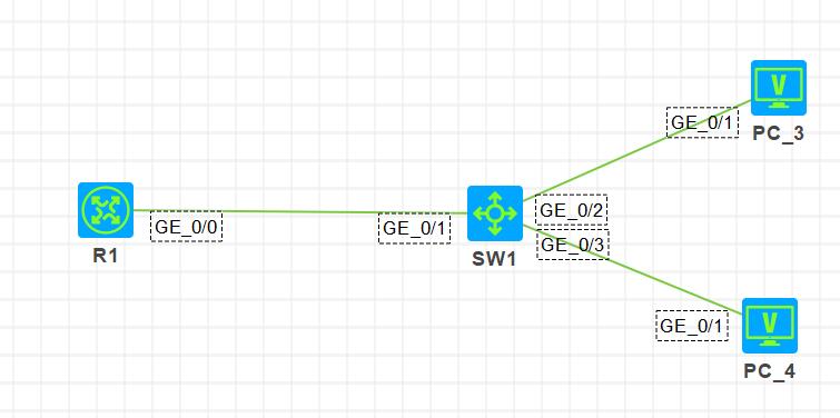
v .交换机连接 PC 的端口配置为边缘端口
1
2
3
4
[SW3-vlan20]int g 1/0/3 [SW3-GigabitEthernet1/0/3]stp edged-port [SW3-GigabitEthernet1/0/3]int g 1/0/4 [SW3-GigabitEthernet1/0/4]stp edged-port
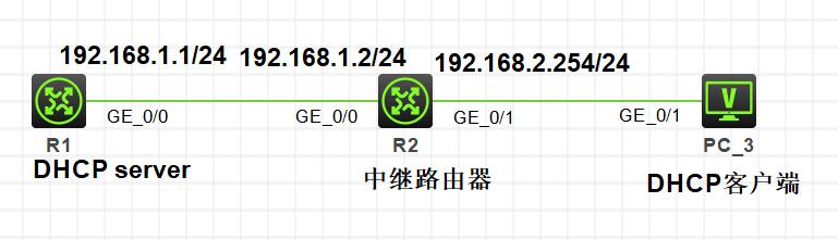
vi .在 SW1 上配置 DHCP 服务,为 Vlan10 和 Vlan20 的 PC 动态分配 IP 地址、网关和 DNS 地址;要求 Vlan10 的网关是 192.168.1.252,Vlan20 的网关是 192.168.2.253
1
2
3
4
5
6
7
8
9
10
[Sw1]dhcp en [Sw1]dhcp server ip-pool 1 [Sw1-dhcp-pool-1]net 192.168.1.0 mask 255.255.255.0 [Sw1-dhcp-pool-1]gateway-list 192.168.1.252 [Sw1-dhcp-pool-1]dns-list 8.8.8.8 [Sw1-dhcp-pool-1]qu [Sw1]dhcp server ip-pool 2 [Sw1-dhcp-pool-2]net 192.168.2.0 mask 255.255.255.0 [Sw1-dhcp-pool-2]gateway-list 192.168.2.253 [Sw1-dhcp-pool-2]dns-list 8.8.8.8
vii .按图示分区域配置 OSPF 实现公司内部网络全网互通,ABR 的环回口宣告进骨干区域;业务网段不允许出现协议报文
1
2
3
4
5
6
7
8
9
10
11
12
13
14
15
16
17
18
19
20
21
22
23
24
25
26
27
28
29
30
31
32
33
34
35
36
37
38
39
40
41
42
43
44
45
46
[SW1]ospf router-id 11.11.11.11 [SW1-ospf-1]area 1 [SW1-ospf-1-area-0.0.0.1]net 11.11.11.11 0.0.0.0 [SW1-ospf-1-area-0.0.0.1]network 192.168.1.252 0.0.0.0 [SW1-ospf-1-area-0.0.0.1]network 192.168.2.252 0.0.0.0 [SW1-ospf-1-area-0.0.0.1]network 10.1.2.1 0.0.0.0 [SW1-ospf-1-area-0.0.0.1]network 10.0.0.6 0.0.0.0 SW2: [SW2]ospf router-id 12.12.12.12 [SW2-ospf-1]area 1 [SW2-ospf-1-area-0.0.0.1]dis this area 0.0.0.1 network 10.0.0.10 0.0.0.0 network 10.1.2.2 0.0.0.0 network 12.12.12.12 0.0.0.0 network 192.168.1.253 0.0.0.0 network 192.168.2.253 0.0.0.0 R1: [R1]ospf router-id 1.1.1.1 [R1-ospf-1]area 0 [R1-ospf-1-area-0.0.0.0]network 1.1.1.1 0.0.0.0 [R1-ospf-1-area-0.0.0.0]network 10.0.0.1 0.0.0.0 [R1-ospf-1-area-0.0.0.0]network 10.0.0.14 0.0.0.0 [R1-ospf-1-area-0.0.0.0]area 1 [R1-ospf-1-area-0.0.0.1]network 10.0.0.5 0.0.0.0 R2: [R2]ospf router-id 2.2.2.2 [R2-ospf-1]area 0 [R2-ospf-1-area-0.0.0.0]network 10.0.0.18 0.0.0.0 [R2-ospf-1-area-0.0.0.0]network 2.2.2.2 0.0.0.0 [R2-ospf-1-area-0.0.0.0]network 10.0.0.2 0.0.0.0 [R2-ospf-1-area-0.0.0.0]area 1 [R2-ospf-1-area-0.0.0.1]network 10.0.0.9 0.0.0.0 R3: [R3]ospf router-id 3.3.3.3 [R3-ospf-1]area 0 [R3-ospf-1-area-0.0.0.0]network 3.3.3.3 0.0.0.0 [R3-ospf-1-area-0.0.0.0]network 10.0.0.13 0.0.0.0 [R3-ospf-1-area-0.0.0.0]network 10.0.0.17 0.0.0.0 [R3-ospf-1-area-0.0.0.0]net 192.168.3.254 0.0.0.0 业务网段不允许出现协议报文: [SW1]ospf 1 [SW1-ospf-1]silent-interface Vlan-interface10 [SW1-ospf-1]silent-interface Vlan-interface20
viii .R1 上配置默认路由指向互联网,并引入到 OSPF
1
2
[R1]ip route-static 0.0.0.0 0 202.100.1.1 [R1-ospf-1]default-route-advertise #把默认路由引入到ospf传递邻居学习
ix .R1 通过双线连接到互联网,配置 PPP-MP,并配置双向 chap 验证
1
2
3
4
5
6
7
8
9
10
11
12
13
14
15
16
R1、Internet: [R1]int mp 1 [R1-MP-group1]int s 1/0 [R1-Serial1/0]ppp mp mp 1 [R1-Serial2/0]ppp mp mp 1 [R1]local-user zhangdaye class network New local user added. [R1-luser-network-zhangdaye]pass sim Qwer123456. [R1-luser-network-zhangdaye]ser ppp [R1-luser-network-zhangdaye]int s1/0 [R1-Serial1/0]ppp authentication-mode chap [R1-Serial1/0]ppp chap user zhangdaye [R1-Serial1/0]int s 2/0 [R1-Serial2/0]ppp authentication-mode chap [R1-Serial2/0]ppp chap user zhangdaye
x .配置 EASY IP,只有业务网段 192.168.1.0/24 和 192.168.2.0/24 的数据流可以通过 R1 访问互联网
1
2
3
4
5
[R1]acl basic 2000 [R1-acl-ipv4-basic-2000]rule per source 192.168.1.0 0.0.0.255 [R1-acl-ipv4-basic-2000]rule per source 192.168.2.0 0.0.0.255 [R1-acl-ipv4-basic-2000]int mp1 [R1-MP-group1]nat outbound 2000
xi .R1 开启 TELNET 远程管理,使用用户 abc 登录,密码 abc,只允许技术部远程管理 R1
1
2
3
4
5
6
7
8
9
10
11
12
13
14
[R1]telnet ser en [R1]local-user abc New local user added. [R1-luser-manage-abc]pass sim abc [R1-luser-manage-abc]pass sim 123456789. [R1-luser-manage-abc]ser telnet [R1-luser-manage-abc]authorization-attribute user-role level-15 [R1-luser-manage-abc]qu [R1]user-int vty 0 4 [R1-line-vty0-4]authentication-mode scheme [R1-line-vty0-4]qu [R1-acl-ipv4-basic-2000]acl b 2001 [R1-acl-ipv4-basic-2001]rule per source 192.168.2.0 0.0.0.255 [R1-acl-ipv4-basic-2001]telnet server acl 2001
转载于邓方鸣-在线文档库
转载目的:学习